Mixed Bending Geometry for the DHR/AR Rheometer
General Information
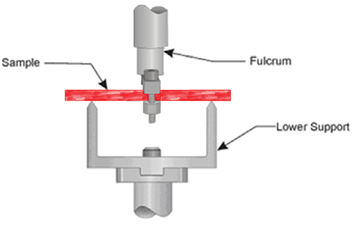
Mixed dual bending holds a solid rectangular sample in a horizontal position. The support frame on the motor supports the sample ends freely, while the transducer clamp grips the center of the sample. Mixed single bending holds the solid rectangular sample in a horizontal position on one side with the transducer clamp. The other end is supported freely on one side of the support frame. Select one of the two larger frames to support the sample and the medium clamp (6 mm) to clamp the sample on the transducer side. Note that the length is pre-set.
Available Sizes
The following are the available frame and clamp sizes for the clamped bending single and dual cantilever.
Mixed Bending Single Cantilever
Frame = 25 mm, 40 mm
Clamp = 2 mm
Clamped Bending Dual Cantilever
Frame = 25 mm, 40 mm
Clamp = 2 mm
Applicable Environmental Systems
Furnace (ETC)
Recommended Sample Dimensions
To prepare samples that fit within the physical constraints of the geometry, the following are the recommended sample dimensions:
- L = 45 mm maximum (depends on the frame size)
- W = Up to 6 mm optimal, 12 mm maximum
- T = Dependent upon E*
Sample Testing Limits
The suggested sample dimensions give the recommended range for sample geometry based on the limitations of the size of the test geometry. Not all specimens should be tested at the maximum stiffness geometry. Extremely rigid samples with a very high modulus (such as highly-filled polymers or reinforced composites) may require a more modest geometry to obtain an instrument operating range where useful data can be expected. A single point test using the desired geometry should be used to fine-tune sample parameters and geometry selection. If too much force is required or the measured strain is significantly lower than the commanded value (which indicates that the transducer compliance may be too large to accurately correct), the specimen should be made thinner, narrower, or longer to obtain better results. If the specimen still cannot be tested practically, it may be necessary to use a different testing geometry, (such as three-point bending) for very high modulus samples, or a tensile geometry for very thin or low modulus sample.
The ETC is a radiation oven with the solid sample and temperature probe in different locations - thus the actual temperature of sample and probe may be different. The difference varies with the sample thickness and the applied heating rate. In this case the furnace temperature needs to be calibrated in order to monitor the correct sample temperature (see also Offset and Span Calibration for DHR/AR).
Installing the Geometry and Loading the Sample
Installing the Geometry
Follow these instructions to install the geometry. Refer to the figure below for geometry component identification.
- Use the Raise to loading gap button to raise the stage to the loading position.
-
Install the lower smart swap geometry with the 25 mm (three point bending) frame attached. Install the alignment tool onto the frame.
-
Attach the upper (cantilever) geometryand tighten the draw rod ( See also Fitting a Geometry on the DHR/AR). Note that the upper clamp is not a smart swap geometry.
-
If this is the first time you are using this geometry, use the Geometry Wizard to configure and define the parameters for this geometry. Otherwise, select the appropriate geometry from Geometry on the Experiment ribbon tab.
- With the Down button on the keypad, lower the upper geometry (clamp removed) into the slot in the alignment tool. In TRIOS, set the gap to zero from the Instrument panel using the Tare button.
- Next, run the axial mapping calibration from the File Manager >Geometries > Calibration. Use the Read Alignment Position to set the alignment position.
- Manually move the upper geometry to allow it to rotate freely. On the Instrument Motor panel, align the upper geometry with the Move to alignment position
 button. Then click Calibrate to perform the axial mapping.
- When complete, raise the stage to provide room to load the sample. Remove the alignment tool and mount the 30 mm frame to the base, if required.
Loading the Sample
Refer to the figure below for an illustration of the geometry with a sample loaded.
- From the Motor Instrument panel, click the Move to alignment position button to align the upper test fixture.
- Slide the sample onto the center clamps.
- Tighten the center clamp before making contact with the support frame.
-
Once sample has been fully tightened, adjust stage position to obtain the desired Normal Force meter indication (load) or activate axial force control to adjust the static normal force (see also Axial Force Guidelines).
Recommendations for Setting Up the Procedure
- Before starting the test procedure, make sure that the test fixture is aligned and locked.
- If temperature tests are to be performed, use axial force control from the Instrument Control panel to pre-load the sample before starting the test and insert a Conditioning Options step in the procedure to maintain the axial force control during the test.
-
For low temperature testing, manually re-tighten the clamps when cooled to temperature, before starting the test.
Equations
Single Cantilever
Strain Constant

|
Stress Constant

|
Shear Factor
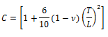
|
Variables
W= Width of sample
T= Thickness of sample
L= Length of sample
|
Dual Cantilever
Strain Constant

|
Stress Constant

|
Shear Factor
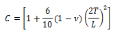
|
Variables
W= Width of sample
T= Thickness of sample
L= Length of sample
|
Back to top
